Transformerless power supply to glow three RGB LED light
In the world of electronics, transformerless power supplies are a nifty way to convert AC voltage to low DC voltage without the use of bulky transformers. These types of circuits are typically used when low current is needed, and space and cost constraints exist. In this blog post, we’ll walk through a simple transformerless power supply design using a 470nF capacitor to power 3 RGB LED lights from a 230V AC source.
Caution: Safety First
Before proceeding, it's important to remember that working with AC mains power can be dangerous. Make sure to take necessary precautions:
- Always disconnect power before making any changes to the circuit.
- Use insulated tools when working with high voltage.
- Make sure your circuit is properly insulated and housed once complete.
This is not a beginner's project, so prior experience with electronics is recommended.
Components Required
- 470nF 400V polyester film capacitor (C1)
- 1MΩ 1/4W resistor (R1)
- 4 x 1N4007 diodes (for a bridge rectifier)
- 470uF 25V electrolytic capacitor (C2)
- Zener diode (9.1V, 1W) (D5)
- 3 RGB LEDs (common cathode or common anode)
- PCB and soldering tools
How It Works
In transformerless power supplies, the key component is the capacitive dropper circuit, which limits the current from the high voltage AC supply. A capacitor (C1) is used to reduce the current flow, and the remaining components help to rectify, filter, and stabilize the DC voltage output, which powers our 3 RGB LED lights.

Circuit Design
Step 1: Capacitive Dropper
The 470nF capacitor (C1) limits the AC current. At 50Hz, a 470nF capacitor offers reactance that limits the current to a small value. The exact amount of current depends on the capacitor value, input voltage, and AC frequency.
The capacitor's reactance is calculated by the formula:
Where:
- = frequency of the AC supply (usually 50Hz)
- = capacitance (470nF in our case)
At 230V AC, the current through the capacitor will be reduced to a safe level.
Step 2: Bridge Rectifier
A bridge rectifier made with 4 diodes (1N4007) converts the AC voltage into pulsating DC. This is crucial since LEDs work on DC.
Step 3: Voltage Regulation
To regulate the voltage to a safe level for the LEDs, we use a Zener diode (9.1V). It clamps the voltage to around 9V DC, which is sufficient for powering the RGB LEDs.
Step 4: Smoothing Capacitor
A 470uF electrolytic capacitor (C2) smooths out the ripple from the rectified DC. This provides a more stable DC voltage, which is necessary for the LEDs to operate without flickering.
Circuit diagram 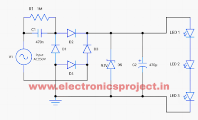
LED Connection
- RGB LEDs are connected to the output of the power supply, all three LEDs are connected in series with each other
How It Powers the LEDs
- The AC input is first dropped in current by the 470nF capacitor.
- The bridge rectifier then converts the AC signal into DC.
- The Zener diode ensures that the voltage does not exceed 9V DC, making it safe for the LEDs.
- The RGB LEDs will glow as the circuit provides enough current and voltage to power them without damaging the components.
Final Thoughts
This simple transformerless power supply design using a 470nF capacitor offers a compact and cost-effective way to power 3 RGB LED lights. While efficient, keep in mind that transformerless supplies are only suitable for low-current applications and come with significant safety concerns due to the direct connection to mains voltage. Always handle with caution, and make sure the final circuit is enclosed in a well-insulated case.
With careful construction, this DIY project provides an easy way to light up RGB LEDs with minimal components, offering both a learning experience and a practical output.
Disclaimer
This circuit involves working with high voltage (230V AC), which can be dangerous. If you're not experienced or comfortable with working on such circuits, it's best to consult a professional.


Comments